iCEcube2 Guide
This guide quickly shows you how to synthesize a design and generate a bitmap using iCEcube2. For more detailed information, see the official iCEcube2 User Guide published by Lattice Semiconductor.
Installation
- Download iCEcube2 and obtain a free license from https://www.latticesemi.com/iCEcube2.
- Save the
license.datfile somewhere safe (such asC:/lscc/license/on Windows). You'll need this file in the next step. - Finally, install iCEcube2.
Folder Structure
You can organize your files in any way that makes sense for your project. It's good practice, however, to keep your source files independent from your vendor's tool files. This makes it easier to migrate your designs should you ever change vendors.
For most of our projects, we use a folder structure similar to the one shown below:
my-project/
├── icecube2/
├── src/
└── sim/
The icecube2 directory will be created in the next section.
Download the Project (Optional)
This guide uses a project called my-project which contains a single source file (my-project/src/top.sv) that makes an LED blink once per second.
If you would like to follow this guide verbatim, you can download and extract the eth4k-demo-guide.zip file.
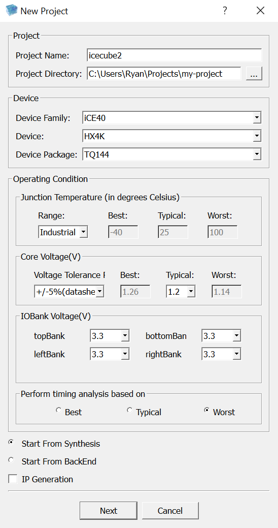
Creating a New Project
- Launch iCEcube2.
- In the top left corner, click
File > New Project. - Set
Project Nameto something likeicecube2. - Set
Project Directoryto your project's root directory. - Set
Device FamilytoiCE40. - Set
DevicetoHX4K. - Set
Device PackagetoTQ144. - Under
Junction Temperature, setRangetoIndustrial. - Set all four options under
IOBank Voltage(V)to3.3 - Click
Next.
- Add the files from your
srcdirectory using the>>button. You only need to select the files that will be used for synthesis.
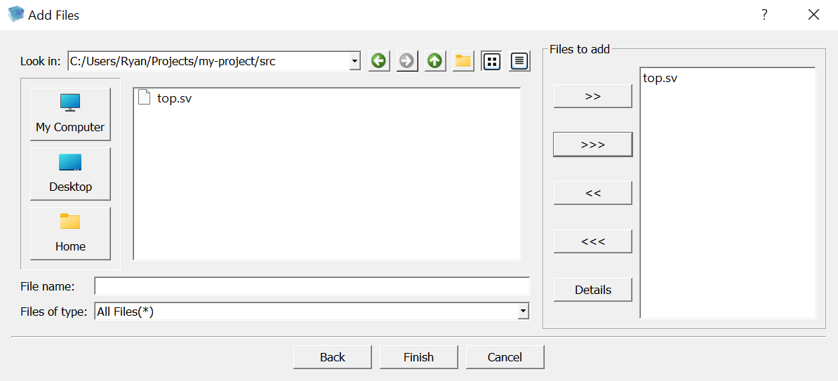
- Click
Finish.
Synthesizing Your Design
- Double-click the
 Run Synplify Pro Synthesis
 - Review the output for any warnings and errors. If all goes well, the output will read
Synthesis succeedednear the end. - Double-click
- Open the
Pins Constraints Editor( ) and enter the pin numbers.
- This editor can also be opened by clicking
Tool > Pins Constraints Editor.
- This editor can also be opened by clicking

- After entering the pin information, save the constraints (ctrl+s). If asked if you want to overrite the existing constraints file, click
Yes. - Double-click
- Double-click
- Double-click
- Navigate to
Output Files > Bitmap > <filename>_bitmap.bin. Right click on it, and clickOpen File Location. - This is the bitmap that you'll flash onto the FPGA, so either take note of this directory or copy the
.binfile somewhere safe.
By default, the bitmap files are stored in my-project/icecube2/icecube2_Implmnt/sbt/outputs/bitmap/.
Next Steps
Now that you have successfully generated a bitmap, you need to flash this bitmap onto the FPGA. Our Diamond Programmer Guide will walk you through this process.